
Background
I picked up this AfterBurner arcade machine back in 2016 from a fellow UKVAC member. It worked, but needed cosmetic attention. There was minor damage to the bodywork, the sideart was torn and the controls felt unresponsive and quite frankly awful. The cabinet had never been stripped down and fully serviced, so that was my first task.


First up, I removed the control panel from the cabinet. The wiring harness had been previously cut and most of the original connectors removed. In these situations I use a spare chocolate block to retain the position of the wiring. It's easier than using labels which have a tendency to fall off.


1/ Dismantle control handle. Splits into two sections. Set aside.
2/ Remove all wiring that runs through central column of control stick.
3/ Remove silver trim from control stick.
4/ Remove front Throttle Decal
5/ Pop start button out through front of plastic. Push it from inside.
6/ Remove top 2 bolts securing plastic from front at top, and 3 from bottom
7/ Pull plastic out and wiggle it round the throttle and stick.

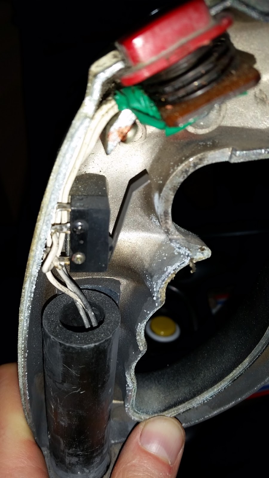
Behind the plastic I found an old damaged part of a pot. Maybe a previous repair was performed badly by the operator, and the wiring butchered in the process? All the wiring was labelled up and deciphered.
There are always some duff bolts that refuse to budge. These generally involve a tedious ordeal to remove them that is disproportionately time consuming. Time to break out the hacksaw blade and blister my finger tips.

I finally separated the main control stick from the wood after about an hour of faffing around with duff bolts that had been bodged together many years ago.
This meant I could finally remove and replace some of the bolts on the front side of this section in order to tighten the whole thing up, highlighted here in pink. (I later realised these bolts were also an operator bodge!)


Let's get that precious metal fitted! I removed the interior from the old assembly and gave the parts I was keeping a good clean in hot soapy water, then raided the baby wipes. Sorry kids. The new assembly looks great though:

In doing so I realised that one of the things that confused me with the original assembly, and one of the reasons I started dismantling it, was an operator bodge. (See the photo where the bolts are highlighted in pink.)
The original operator had drilled new holes through the front of both metal work panels in order to bolt them together directly through the front, presumably to strengthen it following the gigantic crack in the base. However, this was a bad idea as the two pieces of interior metalwork need to 'slide' over each other when the vibration motor is used. Bolting them together prevents this. Not only that, all the metal filings from drilling the new holes were scattered in the grease in the old metal housing. What a mess!
As always, I found other components that were bad. The orange bumpers were disintegrating badly. You can see them in the base of the interior section here:


Time to order some available NOS parts for the rebuild, including new switches, motor brushes and springs.

I couldn't get every size of bumper NOS, could only find TX-1333 spares. I'm going to improvise and cut some of these down for the others I intend on replacing.

Replace the old bumpers, yuck!

Time to fit a proper Mate N Lok plug to the assembly and work towards getting rid of all the chocolate blocks that were fitted. I'm not sorry to see this lot removed. There were some nice hacks within hacks here, with wires extended and wrapped in electrical tape. Yikes.


I cleaned up all the other components. The majority were dismantled into individual parts, given a good scrubbing and reassembled. I'm pretty sure AfterBurner has used up more of the baby wipes than my kids.
For the throttle, I used car touch-up paint to blacken the visible part of the handle also.


The control panel plastic is also cleaned and ready to go.

The control panel is fully rebuilt. This is pure porn territory now.

Time to fit the control panel back to the cabinet. But first to fix the wiring it connects to. Originally it looked something like this when I opened the cab. The chocolate blocks generally represent missing plugs.


Someone really hated this cabinet in the past. At least I now knew the wiring history. Someone must have literally shut the control panel hinge and snipped all the wiring in one fell swoop.
Anyway, back to the most important job on my list - fixing the goddamn AfterBurner joystick! I bought myself the following thread repair kit from Amazon.


Until you start looking closely that is...


The rest appears identical.


I picked up this AfterBurner arcade machine back in 2016 from a fellow UKVAC member. It worked, but needed cosmetic attention. There was minor damage to the bodywork, the sideart was torn and the controls felt unresponsive and quite frankly awful. The cabinet had never been stripped down and fully serviced, so that was my first task.


Read The Fcuking Manual!
Always a good idea before starting a restoration. In my typical OCD style, I acquired four different upright manuals during this process! All are different, contain some errors and sometimes contradict each other. Hoorah!

One of the better finds was a less common 2ND PRINTING (SP) MANUAL NO. 90500025. It has a Brent Leisure marker on the back.

This edition contains around 40 pages, around 10 more than the standard manual. These cover the exterior cabinet parts in more detail, with additional information dedicated to the European wiring and power supply sections.

Control Panel
The controls worked, but the joystick was loose and unresponsive for such a difficult game. The fire buttons didn't feel great. I removed the front cabinet bolts and peered into the abyss. It's clear in its former life the operator loved: green electrical tape, chopping cables and chocolate blocks. It's also clear that he dismantled the control panel at some point and lost a lot of screws.

I'm pretty sure that's not how it left the factory!
If all else fails, repair with electrical tape?!
The handle was dismantled. One bolt was drilled out. One law of dismantling any component of a cab: at least one bolt or screw will not budge. They had been replaced at some point in the past with ill-fitting ones which didn't help matters.

Inside the handle: more green electrical tape. The switch board didn't look particularly healthy and had been repaired badly in the past with big blobs of solder to repair traces.
Next up was removing the front plastic from the control panel in order to access the internals. Here's what I did to remove the front plastic plate:
1/ Dismantle control handle. Splits into two sections. Set aside.
2/ Remove all wiring that runs through central column of control stick.
3/ Remove silver trim from control stick.
4/ Remove front Throttle Decal
5/ Pop start button out through front of plastic. Push it from inside.
6/ Remove top 2 bolts securing plastic from front at top, and 3 from bottom
7/ Pull plastic out and wiggle it round the throttle and stick.

Behind the plastic I found an old damaged part of a pot. Maybe a previous repair was performed badly by the operator, and the wiring butchered in the process? All the wiring was labelled up and deciphered.
There are always some duff bolts that refuse to budge. These generally involve a tedious ordeal to remove them that is disproportionately time consuming. Time to break out the hacksaw blade and blister my finger tips.

This meant I could finally remove and replace some of the bolts on the front side of this section in order to tighten the whole thing up, highlighted here in pink. (I later realised these bolts were also an operator bodge!)

Every Sega control chassis I've looked at has signs of metal fatigue and this one is no different. The motor vibration and use over the years puts considerable strain on them. Anyone who leaves a vibration motor enabled in a Sega upright cab of this age should be terrified!
Here's the damage I found with regard to the two pieces of metalwork that comprise the chassis. (TX-1354 which sits inside TX-1353). A lot of this wasn't visible at first, but becomes clear after a clean and removing the exterior wood housing.
Here are the usual hairline cracks and fractures on the interior metal. But when flipped over, it's the grand canyon of fractures! The entire control panel is falling apart!


I'm no metallgist, but this doesn't look good...
Thankfully, arcadefixit to the (expensive) rescue. He had NOS of the sacred pieces. I am never telling my wife how much these pieces of metal cost.

In doing so I realised that one of the things that confused me with the original assembly, and one of the reasons I started dismantling it, was an operator bodge. (See the photo where the bolts are highlighted in pink.)
The original operator had drilled new holes through the front of both metal work panels in order to bolt them together directly through the front, presumably to strengthen it following the gigantic crack in the base. However, this was a bad idea as the two pieces of interior metalwork need to 'slide' over each other when the vibration motor is used. Bolting them together prevents this. Not only that, all the metal filings from drilling the new holes were scattered in the grease in the old metal housing. What a mess!
As always, I found other components that were bad. The orange bumpers were disintegrating badly. You can see them in the base of the interior section here:


The two bumpers required are listed differently in the alternate editions of the AfterBurner operators manual which makes life confusing.
Upright manual with AfterBurner logo only on front
- tx-1333 Bumper B --- 4 x Large Bumpers On Base.
- No mention of other 2 smaller bumpers
Upright manual with picture of machine on front
- tx-1372 Bumper D --- 4 x Large Bumpers On Base
- tx-1371 Bumper C --- 2 x Small Bumpers On Joystick Assembly
Time to order some available NOS parts for the rebuild, including new switches, motor brushes and springs.

I couldn't get every size of bumper NOS, could only find TX-1333 spares. I'm going to improvise and cut some of these down for the others I intend on replacing.

Replace the old bumpers, yuck!

Time to fit a proper Mate N Lok plug to the assembly and work towards getting rid of all the chocolate blocks that were fitted. I'm not sorry to see this lot removed. There were some nice hacks within hacks here, with wires extended and wrapped in electrical tape. Yikes.

Here's the control panel reassembled with the first of the new wiring.

Fitted new brushes to the motor. Not that I'm ever going to leave it connected. Sega's motors are now cabinet murderers in my opinion!
The control stick appeared ok from a distance, but up close you can see a lot of the paint was flaking and it was pretty uneven.

Sanded the control stick back to bare metal using a Dremel like tool then went over it with finer grain wet & dry sandpaper. I used grey primer, silver paint and a few coats of clear lacquer. It looks nice.

Internally I replaced both switches and the corresponding springs. Turns out one of the springs already present wasn't an original and was the wrong size. I've also replaced the wiring. As per the photos earlier in the thread, the original thumb switch had also been patched up badly with a combination of solder and green masking tape.

For the throttle, I used car touch-up paint to blacken the visible part of the handle also.

Most tired nuts and bolts get replaced as part of this process. However, those lovely Sega screws get treated to a fresh coat of black paint!!


The control panel is fully rebuilt. This is pure porn territory now.

Time to fit the control panel back to the cabinet. But first to fix the wiring it connects to. Originally it looked something like this when I opened the cab. The chocolate blocks generally represent missing plugs.

My original plan was to connect new Mate N Lok connectors and remove the chocolate blocks completely. I'd studied the manual which helpfully lists the connector pinouts and wiring colours.
However, after removing yet more electrical tape that I thought was acting as an impromptu cable tie, I found that at least 8 wires had been damaged, probably trapped in the control panel mech, and almost destroyed at some point in the past, many of these were the 'good' wires still attached to connectors. Bugger. Some examples below.
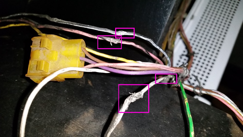
Some of the cuts were quite far into the harness. There simply wasn't enough good wire left for me to just add new connectors, and I wasn't willing to build an entirely new harness from scratch. Crimping pins with my head halfway in the machine wasn't proving particularly easy. I extended the wiring where necessary with chocolate blocks, but also added new connectors. In theory I can now connect up the refurbished controls when they are complete.

Anyway, back to the most important job on my list - fixing the goddamn AfterBurner joystick! I bought myself the following thread repair kit from Amazon.

I didn't need to completely drill out the existing holes as recommended in the kit manual. They had already worn way larger than M5 bolt size. I was worried at this stage that the existing holes would be beyond repair.
I used a tap wrench to cut a new thread:

I then screwed the new coils into place. Here's one going in:

I finally reassembled the handle and screwed the intended M5 bolts back in.

Wow, at the moment the handle is completely tight. It's gone from a load of flappy nonsense to something totally playable. Let's hope it stays that way!
Baseboard
I decided to press ahead with sorting the base board out. I was reluctant to get started on this, as the cab was playing nicely. But it at least needs a good clean up and the bottom of the cab was filthy.

Washed the DC 12V PSU in the sink. Recapped the entire board whilst I had it out. I tested the old caps on my meter and they all seemed within acceptable range so looks like those old caps survived well.
Cap List
35v 2200uF 85c 18mm diameter
35v 2200uF 85c 18mm diameter
16v 2200uF 85c 10mm diameter
50v 10uF 105c
50v 10uF 105c
50v 10uF 105c
All caps manufactured by Rubycon.

- Dismantled and washed most components in the sink
- Recapped the 18V AC to 12V DC power supply
- Found some microscopic live little creatures living under the 5V DC PSU. What were they living on for all this time?
- Replaced most of the bolts and screws, with the exception of the ones in the green SSR (Solid State Relay) boards which appear impossible to remove
- Dismantled and cleaned inside the 5V DC PSU.
- Removed the surface corrosion from the giant transformer. Could have gone further if I'd removed it completely, but didn't fancy desoldering loads of wires.
- Replace crimp terminal connectors for the wiring. The silver (tin?) ones are all fine. The copper ones literally fell apart once removed. Used these.
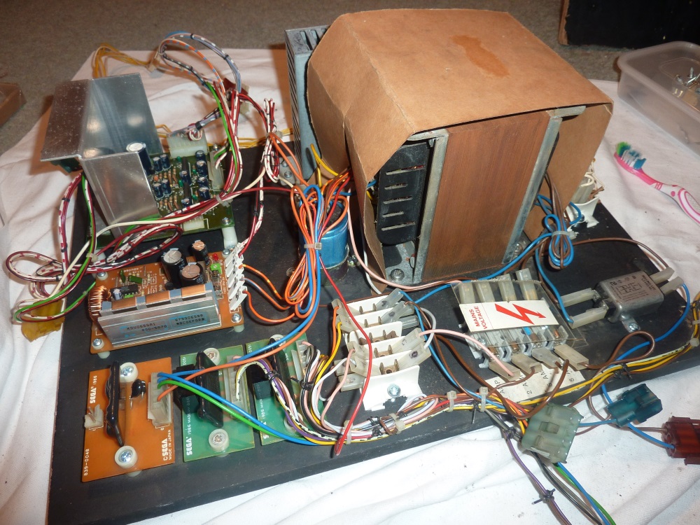
I must say I have a lot of respect to anyone who restores a deluxe Sega machine. Just doing a basic upright is pretty time consuming! These old cabs just get so filthy.
Went a bit crazy and reproduced the 240 Volt stickers. I tried to identify the original font with a number of online recognition tools, but they all failed to provide a solid match. In the end I used my eyes, and went with Franklin Gothic Medium which is pretty close. Guess which is the old one.


Service Switch
Sanded and resprayed the metal housing for the volume control, test switches and circuit breakers. The white paper label had a nicer looking label underneath it, so I just removed it.


PCB & Cage
Sanity checked the PCB to ensure there was nothing scary going on in there. It was all fine.

Programmed and installed the AfterBurner Enhanced Roms.

Made a quick harness so that I could run the PCB outside of the cabinet.

The cage 'door' to access the dip switches was unusable as the cage back was mounted the wrong way round. I corrected this.

Reinstalled everything back in the cab. The cables need some tidying up still once I verify everything is working. It's no longer the filth pit it once was at least.

Cabinet Repairs
Removed the T-Molding, front metal plate and used some Ronseal wood hardener on the corners.


Let's get seriously high on P38 fumes and repair those corners! Wood hardener, pin construction and cardboard template thingie shown below.


Applied the P38 and sanded down:


I dislike repairing wood work with a passion! It's boring, time consuming and incredibly messy to do indoors - dust particles everywhere, sheets, hoovering etc.
It was tricky getting a good finish doing the filling, sanding and painting in situ. Far easier to sand and get good results if you fully gut the cab and tip it on its side. I didn't this time around, but you pay a small price on the finish I think.
I primed and painted with rollers brushes as I was doing this inside my house. The finish isn't bad - obviously not as good as spraying, but given it's just the base it is acceptable.
The T-Molding I bought from swallow amusements was about 2mm wider than the existing T-Molding, and the stuff you can get from t-molding.com. Barely noticeable, but worth bearing in mind if you need to order any.

I replaced the nails that held in the base plate with screws. I also polished the base plate as best I could, but it was pretty scratched.


Bought some M5 hex drive screws. These are great at repairing cabinet problems where captive nuts have been smashed off or lost. It's tricky to install captive nuts in a cabinet unless you fully dismantle it as you hammer them in; whereas these just fasten into the wood and then the M5 bolts screw directly into them.

Fitted a replacement coin box, as the original was missing. Maybe I'll get round to painting it one day..

Lights
Fitted E17 dimmable LEDs to replace the flashing lights. They work nicely. Only difference from bulbs is they glow dimly rather than turn off completely. But it saves bulbs continually going.

Replaced the coin door bulb with a 5V DC wedge LED.

Monitor
Had the monitor serviced by Gunblade. It was working respectably, but the width was pulsing depending on the screen brightness. He replaced a cap and fixed a bad solder joint. Monitor reinstalled, calibrated and looks fantastic (although you can't tell in the photo below). Hard to justify spending any time on a monitor when he offers such a good service. Posted the chassis to him Monday and had it back in the cab 3 days later!

Plastics
Polish, polish, clean. The plastics on this machine really were in nice condition.

Plastics reattached. Cab is beginning to look pretty tasty now.


Sideart
The existing cabinet sides are not too bad...

Until you start looking closely that is...

For the first side, I used a hairdryer to loosen the existing glue. The artwork peeled off in minutes. However, the cabinet was left covered in sticky glue residue. I used a dry cloth and applied WD-40, which works wonders when it comes to removing old glue. It pretty much causes the glue drop off the cabinet with some gentle rubbing. The downside is that this has the potential to be a messy process if you're not careful, as you end up with oily goblets of glue dropping everywhere. Here I am, halfway through this process.


For the second side, I decided to try and peel the artwork slowly off. This was exceptionally fiddly and took about five times as long as the hairdryer method, but left little to no glue residue. So overall, this method was a net positive as there was no additional work required.
I purchased the reproduction artwork from thisoldgame. The quality is great, but it took around 4 months to show up.
The only difference I noticed was the sky colour, which is lighter in the repro (right hand side). That being said, who is to say that the existing sideart was consistent in terms of colour palette.

The rest appears identical.

After painting some dings and cleaning the sides again, I applied the sideart using the dry method, with the cabinet fully upright. Usually I get someone to help me with this, but my wife was already looking after the kids so I flew solo!


And that's it for now. There are still some small jobs to do, but the game is playing great!
7 comments:
Looks amazing. Great job!
Such dedication - great result.
Hello,
I got a Monaco GP board and I'm thinking on convert it into a After Burner 2 (AFAIK, it is the same hardware).
Do you think it's feasible?
Yes, totally possible if you can program the EPROMs. And there are a lot! You will also need to source a standard 68k processor to replace the security equivalent.
Hi, I'm restoring an AfterBurner myself now and I wanted to ask you where did you find the bumpers, mine are as bad as yours.
Thanks
Could well have been arcadefixit.com from memory.
sadly it doesn't look to have them anymore
Thanks, Ricardo
Post a Comment