Showing posts with label hardware. Show all posts

Friday, May 29, 2020

Sega X-Board Memory Test Software

A set of ROM images to test the RAM ICs and custom chips on Sega X-Board hardware (AfterBurner, Thunderblade etc.). It is more robust than the on-board tests and stands a better chance of running on a dead boardset.

  • It does not require working main RAM to actually run the main RAM test.
  • Remove all sub CPU EPROMs when installing (IC 20, IC 29 etc), as these interfere with the results.
  • It requires a vanilla 68K CPU to be installed, not the FD1094 security processor present on some X-Board games.
  • The palette will be incorrect when used on games other than AfterBurner. But it should still operate correctly. 

This was not previously released, because I hadn't verified the IC labeling on hardware. However, a number of people have already used this software to successfully fix PCBs. Therefore, I figured I should get this out there and address problems as they are reported.

This is based on the OutRun Memory Test. The modified (and messy) source code is available here

The compiled ROM images can be downloaded here

Sunday, December 17, 2017

2 x Power Drift PCB Repairs

I'd accumulated 4 broken or untested Power Drift PCBs. All four completely black-screened and showed no signs of life. I decided it was time to try to get at least one of them working. They are difficult boards to find working and I've always fancied playing the game in my OutRun cab.

Board 1 (The Easier Repair)

The Y-Board is complicated, using 3 68k processors, a z80 for sound and loads of custom chips. So when faced with a dead board, there are a lot of potential candidates. Using the scope, I could see the main 68K CPU was resetting every few seconds. There seemed to be good activity on the data and address lines however.

I tested the Main CPU EPROMs first and they all seemed to be bad?! To be honest, I don't know how much I trust the GQ-4X with 27C1000 EPROMs.... it seems inconsistent. But anyway, all the NEC D27C1000 branded ones failed romident. I programmed some new ones, and pinched a few others from one of the other spare PCBs.

The board then booted into life, but with lots of graphical corruption. Amazing - I've never had such an easy fix before. However, the game completely crashed after a short period of time.

Using the scope again I could see that the 'Sub X' CPU (Mame driver naming) had no activity on the data or address bus. The 'Sub Y' CPU seemed to be behaving sensibly. At this point I replaced ALL the NEC branding EPROMs for both CPUs.

The game then ran consistently without crashing, however there were occasional graphical errors.

I swapped the lower video PCB out with one of the other spares and this solved the remaining graphical issues. Unfortunately it was quite late at this point and I forgot to take photos of my progress.

So there you go - not really the most technical fix-log ever. But a fix is a fix, and I'll have a poke around the remaining 2 PCBs next. I also need to hook up some controls.


Board 2

Now that I had a fully working boardset from the previous repair it was easy to establish that I had 3 broken CPU boards and 3 partially working video boards with graphical errors remaining.

Picture shows the CPU board (courtesy of arcade.ym2149.com)


The CPU Board contains 3 x 68000 processors. These and known as the main CPU, X CPU and Y CPU. I initially investigated the main CPU signals and bus with my scope. I verified the EPROMs, then checked the SRAMs and buffer logic chips to ensure they were doing something sane. The PCB itself was filthy. Amusingly, pretty much every EPROM I pulled had a dead spider under it. One of them actually made me jump as it flew out at me with the chip! I was finding physical bugs, but no technical bugs, so it was time to move on!


I moved onto the X CPU. After working my way around the chips in the circuit I found little activity on the SRAM data and address lines. I piggybacked the first pair of SRAMs at IC 84 and IC 85, and to my delight the board booted. At this stage there were no zoomed sprites at all and lots of graphical errors. Only some of the static 2D sprites displayed correctly. However, I could coin up and hear sound and music which proved  the main 68000 circuit and Z80 sound circuit were healthy.


I put the board into test mode. Things weren't completely readable but the screen could at least be compared with MAME. The tests reported 4 SRAMs and 2 EPROMs were bad in the X CPU circuit. However, this report couldn't be fully trusted at this stage due to the piggybacked RAMs. I tested the EPROMs that were reported bad and found them to fine to prove this point.


I socked two replacement 6164 SRAMs at IC 84 and IC 85.


 I tested the old ones out of circuit and found them both to be faulty.


I booted the board again to verify the replacements were working. I then decided to piggyback the remaining two SRAMs that were also reported faulty by the internal tests at IC 82 and IC 83. They were right next to the previous bad ones and also similar Toshibas, so could in theory be bad as well. At this point I managed to see glimpses of the zoomed and rotated sprites that make up the game's road layer and backgrounds. The rotating Power Drift logo also showed signs of working.


After replacing IC 82 and IC 83, the game was running with scaled sprites.


The self-test now reported that everything was ok, including the video board SRAMs it had previously declared bad.


However, the game wasn't running correctly yet. At this point I swapped in the other video boards I had available to find the least broken candidate. This also proved that the CPU board was 100% worked and the remaining errors were on the lower video board.

This was all well and good, but I had no easy way of accessing the lower video PCB. This is where a set of interconnects built by UKVAC's ColinD came in handy. I'd had these sat in a box for months, but never had the need to construct them. I soldered them together, and could now separate the PCBs whilst powered up.


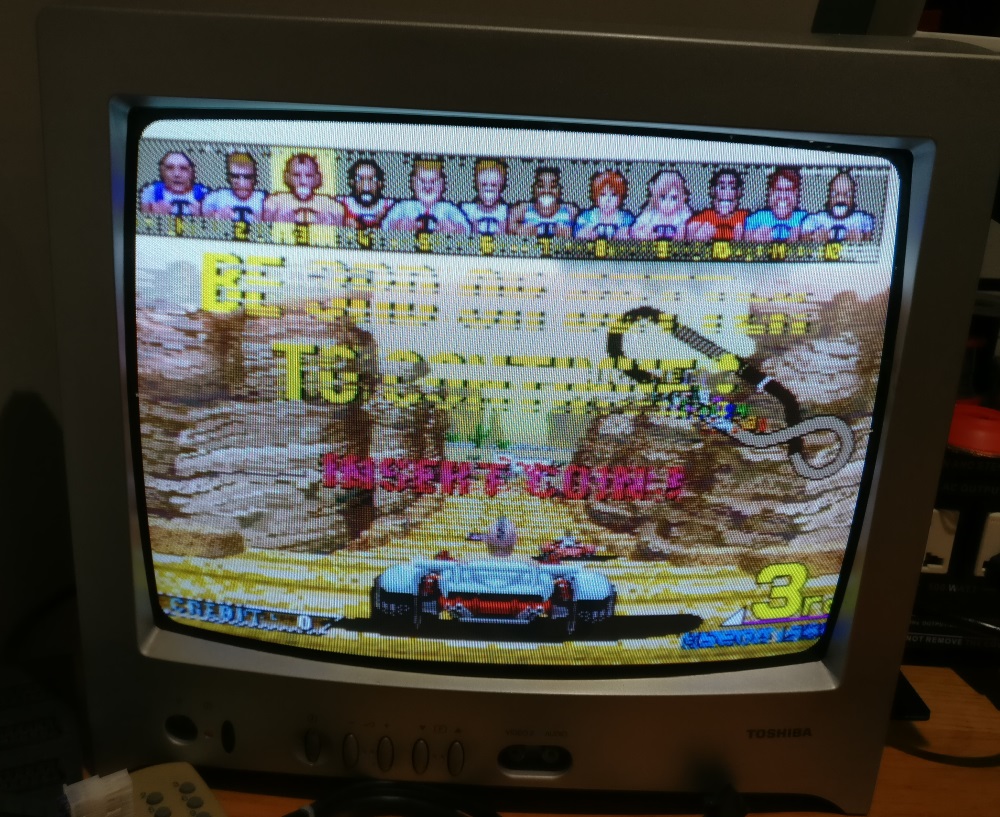
Now here's where things got quirky. The video boards all exhibited problems with the 2D static HUD sprites. For example, the "BE 3RD OR BETTER TO CONTINUE" graphic had jailbars. This would often be the sign of a bad line on an EPROM, SRAM or logic chip. I knew the SRAMs were good from the on-board tests so I turned to the EPROMs which weren't tested by the on-board routines.


Using my Sega Sprite Viewer tool, I could tell that these graphics were located in two interleaved EPROMs: epr-11789 at IC 16 and epr-11791 at IC 14.


As a first check I verified the EPROMs out of circuit. I had a little trouble reading them, but eventually got a good read. I put this down to the GQ-4X being a little quirky with 27C1000 EPROMs. I've had trouble in the past with them despite using the recommended jumper wire.

However, I was now really stumped as to what the problem was. I swapped in two EPROMs from another broken video board and got a different visual problem in the same area. I swapped another set in from a different video board and got yet another different problem with the graphics!!

I was really pulling my hair out and spent quite a lot of time checking various stuff. As a last resort, I programmed a new EPROM.


And what do you know... Isn't that unbelievable that EVERY video board had the same damaged EPROM? Maybe there's something about the board's construction that causes this.


Next step will be to verify the controls. I'll do this once the following PCB arrives from Alex that allows you to connect a PS2 controller on the bench for testing and a lot of other nifty stuff. But we'll cover that another time! I may have a (short) break from fixing Power Drift boards for now.


Monday, June 12, 2017

Super HangOn PCB Fix Log

I purchased up the internals of a Super Hang On shell a few months ago. The package included an untested PCB that, judging from the photos he sent, had suffered a tough life. On arrival, the PCB booted and ran which was a great start, but no road was visible.


On inspecting the underside of the PCB, it was a real dog's dinner with repairs all over the place. It looked like someone had gone wild gunshotting parts of the circuitry to fix a previous problem. There were jumper wires connecting parts of the PCB where traces had been damaged. At this point I wrote to Mark at Retroclinic who kindly provided details of the work he'd done on the board, so I can distinguish his work from the chaos that had also occurred.


The top PCB is responsible for road rendering and is identical to the OutRun PCB, including the PALs. Super Hang On is similar to OutRun but with inferior sprite hardware, which is why the scenery is rather sparse in comparison from a gameplay point of view.

I quickly ported the OutRun test ROM to the Super Hang On hardware. This involved changing a number of memory addresses as well as the memory mapper configuration code. This proved that both the Sub CPU and Road RAM was fine. (For those waiting on the OutRun test ROM, it's now with Alex who will be releasing it in due course.)  ignore the sprite hardware failure below, I didn't adapt the code to handle SHO's sprite hardware correctly.


I could now focus on a smaller section of the schematics. I verified the Road ROM which was good. I swapped the PALs responsible for the road mixing and road bit extraction with a known good OutRun PCB to eliminate them from the equation.

Using my logic probe, I noticed that the Output Enable pin of the Road ROM was stuck high, essentially meaning the ROM data was not being used. Using the schematics, I traced the problem back to an LS174 @ IC14 (quad d flip flop). On closer inspection there was some signs of corrosion around its legs.


Piggybacking this chip restored the road circuitry. I mistankenly swapped out an IC downstream beforehand. If I'd used my scope and not been lazy, I would have avoided this.


Shortly after fixing the problem, another issue arose whereby there was a further visual glitch with the road hardware. Notice the colour band in the sky and the blurry road below. I swapped the test ROMs back in and they reported a failure with the Road RAM (or more likely the logic chips connecting them to the CPU). In game it looked like a visual glitch when the hardware performs the Road RAM swap.


However, the problem then vanished! And no amount of pressing on chips, flexing the PCB or power cycles could replicate it. I imagine it could return in the future if a chip is on the verge of failing somewhere, but hard to fix a problem you can no longer reproduce. If anyone has any thoughts on this then let me know.

Turbo OutRun PCB Fix Log

Purchased this OutRun boardset from the states. It was sold as faulty. The seller included some free food, which kept me happy whilst I stared at the black screen it presented me with on boot.


First thing I did was to verify an EPROM with RomIdent. This showed this was actually an OutRun boardset converted to Turbo OutRun.

I then tested the 2 boards against a known good set, and found the lower video PCB to completely working. Fantastic! This saved me building the interconnects that ColinD kindly sent me this time round.


I swapped the security FD1094 processor with a vanilla 68000. I programmed some decrypted ROMs.

I was greeted with the following screen.


Progress, but this was a bit of a red herring. It crashed immediately after this screen. In fact, this screen was an addition of the Japanese decrypted roms I'd happened to use. It's possible that the security processor was still working, but I'll go back and check that later.

I dug out the schematics and found an LS244 with dead outputs @ IC83. This was part of the sub CPU memory addressing. I socketed it and swapped it out, but it didn't make the game boot, although the logic probe showed its pins were doing something at least.

At this point I decided I wasn't going to change any more components without better diagnostic information. I'm slow at desoldering, so shotgunning stuff wasn't a good idea.

I used the OutRun SDK, created by Alex, to code a test tool for OutRun. Alex had already started work on the tool and I made some further modifications. My theory was that I needed a minimal piece of software to test as much of the hardware as possible. The problem with the on-board tests on OutRun, is that they require most of the PCB to already be working in order to use them. So they are mostly useless.

I spent a couple of nights changing the tool so that it would test the 4 Main CPU SRAMS, the 4 Sub CPU SRAMs, Tile RAM, Text RAM, Palette RAM and Sprite RAM.

The tests that Alex had included were far more rigorous than OutRun's onboard tests, with separate address bus and data bus tests.

Screenshot from MAME below, excuse the horrible palette (it's really setup for OutRun not Turbo OutRun)


I programmed this to the boardset and got the following:


The program reported the Sub CPU RAM @ IC 73 was bad.

I also verified that the ICs reported by the program were correct by glitching some of the SRAMs whilst it ran.

After hours of swearing and desoldering (mostly due to the ground plane) I'd removed the offending SRAM and socketed the IC.


Personally, I find these boards an arse to work with. I have a lot of respect for Mark at Retroclinic now.

At this point, the test gave me a different error because the SRAM was completely missing. Promising!


Inserted a replacement SRAM and BOOM - all OK!


Change the EPROMs back to the game and we have attract mode with sound:


Monday, February 22, 2016

Sega Golden Axe Bootleg Fix Log

I pulled a Golden Axe Bootleg PCB out of storage. I hadn't fired it up for 20 years or so.

Unfortunately, it didn't work. The screen was too dark, apart from when the game was performing its windowing effect, where it suddenly displayed at perfect brightness. Sometimes the screen would completely lose sync and go black.


Initially, I didn't hold out much hope. Whilst there are few customs on this boardset compared with the official Sega PCB, there are hundreds of ICs and no schematics.

Top PCB


Bottom PCB


I started by inspecting the board. There was a Fujitsu IC on the top board that was running hotter than the surface of the sun. As Fujitsus have a bad rep, I swapped it out. The new IC ran cooler, but the windowing problem persisted.


I moved around the board shorting pins with my logic probe in an attempt to figure out what area of the board was responsible for the rendering issue.

I struck gold and found an IC with a damaged leg. It was my lucky day. This was data input pin 6 of an 74LS169 chip. This is a 4-bit binary counter. It would make sense for this counter logic to be used in the windowing effect when resizing the display area. To test this theory I quickly connected the damage leg back up and the problem vanished. This was going to be an easy fix!


I socketed and replaced the IC. I powered up the board. It was now completely dead!  I tried a different 74LS169 chip. Still completely dead! I wished at this point I hadn't snipped the legs of the original LS169 and had simply repaired it in-situ.

Suspecting my handiwork fitting the IC socket, I resoldered it for a second time. The board remained completely dead. I was baffled.

I then swapped in a different LS169. The board booted!


I can only presume that a combination of a faulty LS169 I had purchased and some bad soldering on my part caused the board to play dead. Unfortunately I do not have a way to test LS169s ICs out of circuit. The faulty replacement was a 74LS169BN as opposed to a 74LS169AN, but I'm assured they are compatible.

The bootleg has a number of issues, which are probably the result of it being a bootleg as opposed to a fault on the PCB itself:

- The screen momentarily fills with garbage for a frame or so on screen clear
- The sound isn't as clear as an original PCB
- There is no service mode available to test the RAMs and ROMs

Sunday, January 17, 2016

Shinobi System 16B Fix Log

Following my painful success fixing a TMNT PCB, I decided to move on and try another.

I bought an untested (tm) Shinobi PCB from ebay as I like the game.


The PCB was in a dusty state, but was complete.


Of course, the board didn't really work. Although I was pleased to see it booted and did something!

The most noticeable problems:
1/ The graphics either had jailbars or were completely missing
2/ There was no sound. 


The game was actually playable under all those jailbars.


The first thing I did was to remove Sega's FD1094 processor and replace it with a stock Motorola 68000. I reprogrammed the relevant EPROMs. There are also some reports that these boardsets exhibit unpredictable behaviour, including the sound failing, when the battery is on the way out. This didn't fix any of the issues, but gave me the comfort in knowing the board wouldn't die in the future when the ageing processor battery expired.


Graphics

The test mode showed one of the RAMs was bad.


This is the RAM shown below.


I bought a spare from China, and socketed it. Desoldering went a little smoother than the TMNT desoldering marathon, but I still had to snip the legs of the old chip and spend maybe an hour or two on the chip. The end result was pretty clean, so at least my desoldering is improving. I can't say this is a particularly enjoyable part of the hobby for me. 


Unfortunately, this didn't fix the bulk of the issues.

On a positive, the RAM test now passed, and the graphical problems seemed marginally better with less random garbage on-screen. The jailbars remained though. 


At this point, I could tell that it was just the tile graphics that had problems. The sprites seemed fine. I did some highly technical 'pressing on EPROMS' and noticed I could reduce the width of the jailbars with some pressure.

I removed the tile EPROMs and checked them in my reader. One of them was full of junk data and didn't match the expected CRC.


I programmed a new EPROM and the graphics were restored and the game looked perfect. 


Unfortunately, after running the game for about 30 minutes the sprites also developed a problem with lines running through them.

In hindsight, maybe this problem was intermittent as the sprites were also screwed in my original screenshot of the game. 


I used my System 16 Sprite Viewer to determine where the garbled graphics were located. Once again, I found a faulty EPROM and reprogrammed it.


Graphically everything is working again! Phew!

Sound

- I verified the 3 sound EPROMs were good. After all the previous EPROM failures, they were the first thing I suspected. 
- I checked the Z80 isn't in a HALT / RESET state. It seemed to be running. 
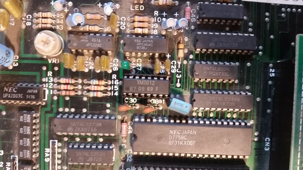
- I could  hear hum from the amp when the pot is turned up. Tapping the logic probe on the outputs of the YM3012 causes audio interference.The amplification part of the circuit is working. However, data wasn't being fed into this chip correctly. So something was going wrong upstream. 
- I tried piggybacking the SRAM used by the sound processor. This didn't change anything.

Using a logic probe, I spotted some bad activity at the YM2151 sound chip The following pins were suspect:

21  Serial Output      
Stuck Low [Connected to DATA on YM3012, should be doing something]

20  Sample & Hold 1    
Stuck High [Connected to SAM1 on YM3012, should be doing something]

19  Sample & Hold 2    
Stuck High [Connected to SAM2 on YM3012, should be doing something]


There was sensible looking activity on the data and A0 pins. Downstream, the YM3012 wasn't doing anything sensible. The analog and channel outs were floating. 

I didn't know which of the two components was faulty, so I ordered both. The output from the YM2151 was clearly borked whereas the inputs seemed sensible. I wasn't entirely sure whether a damaged YM3012 could also be causing this. 

I socketed and replaced the YM3012 first, mainly because it had fewer pins to desolder!


This didn't fix the problem, so I socketed and replaced the YM2151.


This fully restored the audio.


In summary, I replaced:

Desuicide
1 x 68K Processor
2 x EPROMs

Fix Graphics Problems
2 x EPROMs
1 x SRAM

Fix Sound
1 x YM2151
1 x YM3012 (Unnecessary)