What have I been doing for the past 9 months? Well, I recently finished restoring my OutRun Mini cabinet. I posted updates on Jamma+ as the restoration progressed, but here's a more organized summary of what was involved.


The first side plate is also removed. Interestingly this reveals the original artwork hidden under the plate.


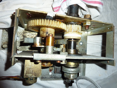


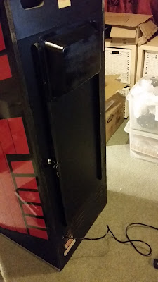
I spray-painted the steering shaft and the metal casing black:


and After:


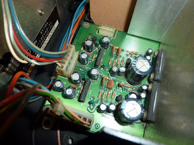





Installed the Enhanced Edition ROMs and a larger capacitor to save the high scores. Time to play!


Phase 1 - Stripping the cabinet down
This proved to be more time consuming than anticipated. Due to the length of time the cabinet had been in storage, bolts and screws were corroded and difficult to remove. Plus documenting, labelling and bagging the components is a considerable task.
My general technique to remove corroded bolts is as follows:
My general technique to remove corroded bolts is as follows:
1/ WD-40 Specialist Penetrant
2/ Wait
3/ Wire brush the Screws/Bolts
4/ Attempt to turn with Vice Grip Pliers
5/ Repeat as many times as necessary. Up to 5 or so iterations.The accelerator pedal bolts were so rusty, you couldn't really see them.
2/ Wait
3/ Wire brush the Screws/Bolts
4/ Attempt to turn with Vice Grip Pliers
5/ Repeat as many times as necessary. Up to 5 or so iterations.The accelerator pedal bolts were so rusty, you couldn't really see them.

This time, no amount of penetrating oil or other trickery was going to remove these bolts. Not that I didn't try every trick I could think of. Drilling them was the only option.

I hit a similar problem with the base-board. Now the base-board bolts into the bottom of the cabinet via some captive nuts (highlighted in pink below). Unfortunately these nuts had been damaged and were no longer secured in the bottom of the cabinet. I decided to turn the cabinet on its side and hold the captive nuts in place whilst turning the bolts.

I had to remove the hacksaw blade due to the tightness to the cabinet and slowly cut these off.

Finally the cabinet is stripped of electronics and I can go wild with a cloth, some soapy water and a splash of bleach. The cabinet was disgusting, so most of the time I had the carpet fully covered with sheeting to protect it.
Turned the cabinet on its side. Tackling removal of the protective plates at the bottom of the machine.

I'd already found 2 x 20ps doing this restoration. Now I add to the collection a 2p, a new 5p and the old 5p which went out of circulation in 1990 ;)

The first side plate is also removed. Interestingly this reveals the original artwork hidden under the plate.

Here you can see that the accelerator pedal was mounted incorrectly - directly into the wood, rather than the captive nuts. This is one reason it proved so difficult to remove.

Old floormat glue-gunk was removed with my wife's hairdryer and a chisel. Worked well.


Phase 2 - Repairing The Cabinet
There was plenty of body-work needed on this cabinet. Nothing was that bad, but there were many small dings, dents, scrapes and other nasty bits. I used P38 bodyfiller and Dolphin Glaze.
The flash makes this look horrendous, but it's as smooth as a baby's bottom if you run your hand over the side of the cabinet! I cleaned the cabinet with alcohol shortly after this...

I started by repairing the crumbling corners. Used wood glue, wood hardener and then nails to reinforce the corner before the P38 car bodyfiller was put to good use.

Used clamped perspex to help build the corners.


The other cabinet corner was an even bigger crumbling mess. I found a few dead wood-lice in the T-Molding groove.

Before sanding and shaping.. looks a mess!

Here's the first corner after sanding, shaping, cutting the T-Molding groove. I'm happy enough, second corner is similar.

Phase 3 - Spray Painting
Apply the Primer...


And then the Satin Black.

Phase 4 - Cabinet Metal Work & Parts
Metal work was sandblasted and powder coated. Before:

After:


The base protector plates were sand blasted and clear zinc plated. Before:

After:

I fitted new grey matting. I opted for grey to match the promotional shot of the mini cabinet (and bring things closer to the deluxe cabinet), rather than the black that it was originally in.

Remember the corroded bolts I hacksawed from the base of the machine, that originally held the base board in place? I replaced the captive nuts with new zinc plated ones.

Phase 4 - Side Art
This side-art is similar to the American mini cabs, which as far as I can tell had genuine vinyl stickers. The UK cabs were stencilled.
One side went on perfectly. The other side I annoyingly had a few issues around the 'A' of the SEGA logo.

Here's a close-up. These aren't air bubbles as such as you can squeeze them out / flatten the vinyl and they vanish. They are areas where the vinyl hasn't stuck correctly and has popped up. I suspect this happened because we repositioned this corner within a few minutes of first sticking and in doing so lost the full adhesive of the glue. Grr.
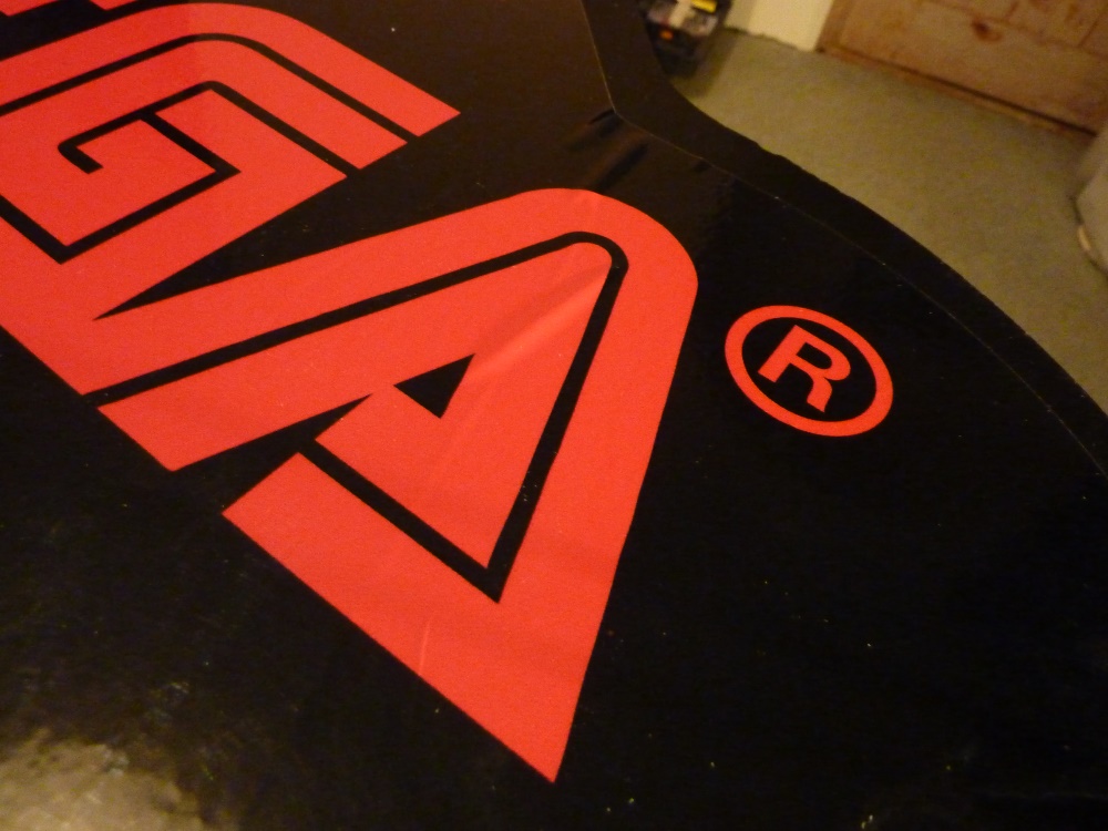
In an attempt to solve this problem, I clamped the art into place with some perspex and waited for 5 days.

I then used a hairdryer to remove some of the remaining kinks. The results aren't OCD perfect, but they are close. Let's hope it stays this way!


Phase 5 - T-Molding
Now the T-Molding I ordered from t-molding.com had a different barb size to the original OutRun T-Molding. It was a lot thinner.
Here are the dimensions from t-molding.com:

Here is a comparison of the old T-Molding I pulled from the cab vs. the new!

I was a bit concerned at first that the new T-Molding was too loose.
I spoke to David (of the better OutRun/Chase HQ restoration threads), who is a little like my OCD cabinet oracle. He told me not to worry and that hammering T-Molding in isn't much fun, who cares about the barb, it's all in the width etc.
One benefit of the looser t-molding was it meant we could lay the entire T-Molding stretch out, and use a stanley knife to cut around the bends. Each time I reached a bend, the T-Molding was removed from the cabinet and recut. Therefore, it was easy to get a good fit.
Finally I had a length of t-molding that fit perfectly and was ready to be glue-gunned in place. Using the glue gun worked well. Any excess glue could simply be scratched off.


Finally, in a bout of OCD I fitted a NOS sticker to the rear of the cabinet from ArcadeFixIt.

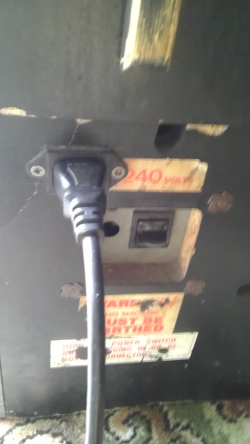
I did try to track down references from OutRun Mini cabinets to compare stickers. However, most cabinets are in bad shape. Cmonkey has one of the better ones. His has an extra 240v sticker as shown below and is fitted with an after-market socket:
Phase 6 - Pedals
Time to restore the pedal assembly! It was pretty grimy.... grease, dust and corrosion everywhere!


I dismantled the assembly and initially washed the components down with a high-powered hose in the garden!
I scrubbed everything until it positively hurt. Baby-wipes, IPA, wire wool etc. I resprayed various components. Even the screws!


I managed to salvage almost everything. The only new part was the accelerator hinge and pin, as the old one was worn. I had the brake pedal chrome plated too.

One thing I got wrong when initially reassembling, was I put the central spindle in the wrong way round. This wasn't immediately obvious, it was so covered in gunk when I disassembled I didn't take note of this, so take care!
The spindle was greased. The other accessible parts I'll grease before they go into the cabinet.


The chrome plated accelerator pedal will be fitted when the unit is mounted in the cabinet.

Phase 7 - Control Panel
The CP installed in the machine was sprayed black. Therefore, I used the plastic from a backup control panel that I purchased as a spare a few years ago.
I used Novus 2 then Novus 1 on the plastics. The results are good, although the plastic wasn't in a bad state to begin with. (Unfortunately, I forgot to take a photo of its appearance before.)
There are a few minor burns and imperfections, but they're not offensive enough for me to warrant doing much more than I have done.


As for the rest of the control panel - let's just say the first step was to take it outside and spray it with a high powered hose!
I dismantled and cleaned the gear lever. One common problem is the compression spring going, which ensures the gear nicely snaps into position. I ordered a new spring.

I dismantled the assembly and cleaned every part. It was pretty dirty before.

After some scrubbing, the end results are reasonably good. A lot of OutRun shifter plates end up slightly bent like the one below. I decided not to try to bend it back into shape. I was a little concerned I'd end up doing as much damage as good. It's not noticeable when mounted on the control panel.

I sanded the silver stick with 800 and 1200 grit sandpaper to remove the rust. It doesn't look new, but it looks decent enough.

I then moved onto restore the steering mechanism. This was a bitch - seized screws in the steering column and other nastiness. Here is the mechanism originally:

For useful reference, here is the order of parts on the OutRun Mini steering shaft. Notice it contains a few additional components over the standard upright to support the solenoid based steering shaker. Left to Right is front to back.

Interestingly/worringly, both lots of steering base metal work I own (from two separate control panels), show signs of metal fatigue. There are cracks around the bottom edges of the metal where the vertical sections join.
It's not really noticeable until you've dismantled the entire mechanism. I doubt you'd notice when it's still screwed to the supporting metal frame. I only noticed when both CPs were completely dismantled and I was scrubbing them clean.


I believe this could be a common point of failure on OutRun Mini cabinets, as a result of the solenoid striking the end of the steering column. I decided to ask my father-in-law to weld the chassis back together. He's a former mechanic and restores cars in his spare time. This is fast becoming a project for the entire family! ;)

The chassis was MIG welded. I cleaned it up as best as I could. I would have needed to get it replated to remove the final blemishes I suspect.

I ordered some replacement 3D printed gears, to replace the original cracked gearing. They seem pretty good. They also come with grease suitable for plastic and the relevant allen keys. One benefit of them is that they are slightly thicker than the original gears.
Here's an example, with the new gear on the right hand side. Notice the metal casing also surrounds the plastic, which also seems a better idea.


The springs included with these gears are slightly lighter than the original OutRun springs apparently. But they seem pretty damn strong to me! I guess my old springs were a bit knackered.
When initially disassembling the steering assembly I used autoglym engine cleaner, a brush and a high powered hose. This removed some of the initial gunk.
Once dismantled I scrubbed the parts some more with baby wipes, alcohol and anything that seemed to work. :)


Some parts had bent out of shape, so needed to be eased back into position!

Here are some before and after shots:


Time to fit the plastic and mount in the cab. I also replaced the non-original 'fruit machine' start button and I soldered wiring terminals For the NOS Sega LED Button.

Plastic Polishing!

NOS Wheel fitted. I bought this over 10 years ago on Ebay. It's finally being used!!

Phase 8 - Fan, Speakers and Solenoids
Next the fan area. Here's how it originally looked. Grubby!

The fan totally seized!

- I bought a new fan of the same spec off ebay.
- Rewired the cable to the new connector.
- Sprayed the grill
- Replaced the holding bolts and nuts
- Removed the staples that held the grill in place, and simply used the new bolts.
The original cabinet didn't have the holes drilled accurately for the fan, and it was bodged into place. I used a small file to widen the holes and mount the fan more accurately.

Cleaned and fitted the solenoid. This is responsible for shaking the steering wheel when you drive off-road or crash.
It works but, somewhat sadly, I'll be leaving it fitted but unplugged. It's like a pneumatic drill going off in the cabinet. And following the cracks and damage in the two steering chassis I got hold of, I don't think it's wise to be whacking them in such a manner!
Before:

and After:

Replaced old speakers (top) with new speakers (bottom). Sprayed the speaker grills black also.

I also sanded and polished the service plate metalwork.

I've been reorganizing all the wiring as well. All wires have been IPA cleaned and babywiped. Connectors cleaned etc. The original wiring in the cabinet was a dogs dinner. I've no idea how you were supposed to service one of these cabinets easily. The way in which wires were grouped with cable ties seemed to be for cosmetic reasons, as opposed to anything logical.
I can almost taste the 175, 719th game!!!
Phase 9 - Electronics
Back to the base-board, which contains the PSU, monitor transformer and sound amp. It fell out of the cabinet in an unholy ceremony of dust.

It was actually worse in the flesh than it looks here.
I removed the main components from the board, dismantled the PSU and scrubbed for a long time with anti-static brushes, toothbrushes, baby wipes and so forth.


It's the moment of truth. I power up the base-board in isolation and reach for the multimeter. I read 5.3V at the end of the wiring harness that will connect to the PCB. Wahay, it works!
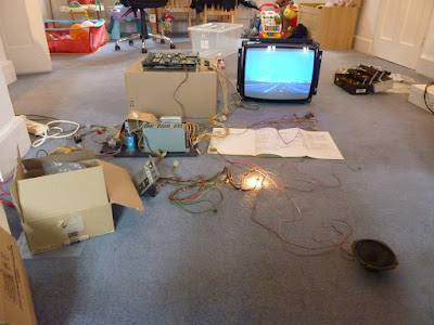
I powered up all the electronics. First time since the 90s.
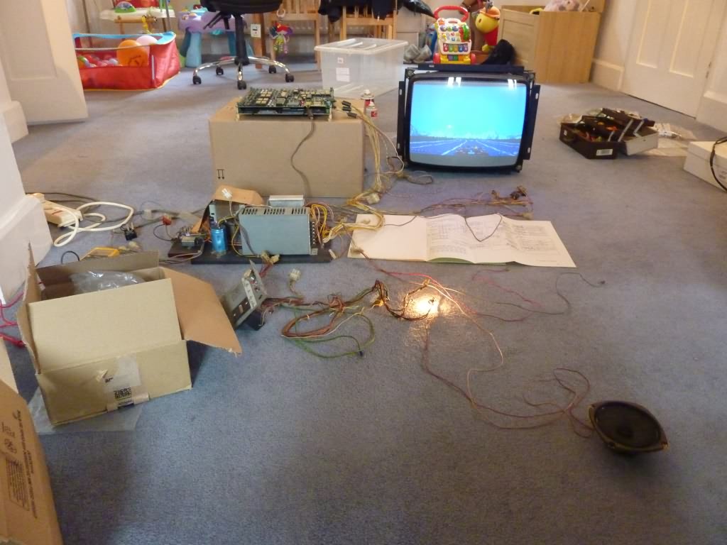
At first, the monitor refused to switch on. Turns out the sockets on the rear were a little corroded. After some coaxing, a reassuring static fuzz could be heard.
At first the monitor was missing red. Then it was missing all colours aside from red. Tapping the contrast control on the rear, which looks a little damaged helped address this temporarily.

The Hantarex 900E monitor also looks like it needs a cap-kit as the image is badly compressed. The monitor was assigned to my Dad to fix. Respect to my Dad! The monitor has no screen burn and when the image works it looks great.
The initial problems included:
- Input Board: Contrast control on monitor has been snapped off (see image below)
- Input Board: Faulty loose coil
- Colours come and go
- Vertical Collapse
- Horizontal Expansion

The monitor had the electrolytic capacitors replaced. There were still some problems with the loss of various colours, but the situation was improving:

Sent the monitor to GunBlade for further investigation. In fact he got it fixed the same day he received the chassis. Top marks!
Here is a log of everything he fixed:
- Open circuit horizontal drive transformer
- A few bad pots, including a burnt out pot on the neck card which caused occasional colour loss
- A crack in one of the tracks on the neck card
- A couple of caps missed
- Replaced the 15w load resistor with a used but good 30w
- Flyback had a bit of dirt inside the screen volts pot.
This now means the picture looks great and I could start fitting the electronics back into the cabinet.
Phase 10 - Marquee & Light
Onto the marquee. Interesting to note the different colours of the mini marquee below. The girl's hair is more ginger; the exterior of the OutRun logo is black; the road is paler.

Time to carefully clean this up. I gently wiped the rear of the marquee with baby wipes and a cotton cloth. It was covered in a layer of yellow grime and black paint. You can see an in progress shot below. This took about 2 hours!

Finished!

I used Novus 2 and 1 on the front.

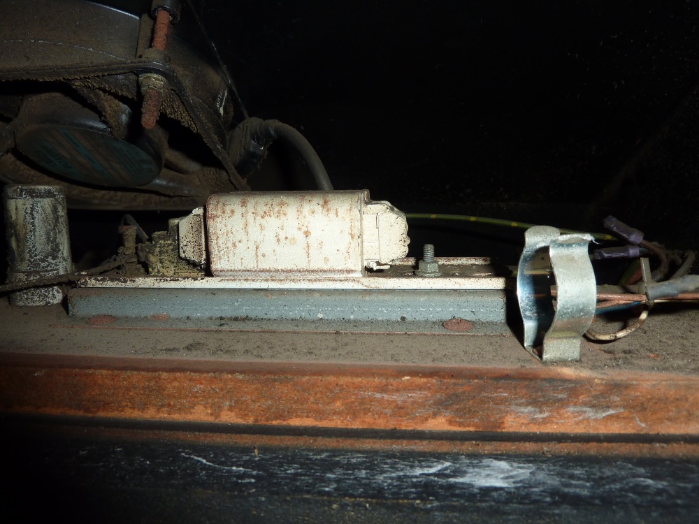
I decided to replace the fluorescent lighting with an LED replacement. Mainly because the ballast causes interference with the monitor and makes the picture wobble slightly. Here's how things originally looked - spider central!
I went for a 400mm LED strip light from CPC. I managed to directly mount it using the existing captive nuts in the cabinet. Therefore, I can easily swap back to the original lighting unit if I want to. Plug and play. Fantastic!

Phase 10 - Monitor & Glass Bezel
Ffollowing a spray of window cleaner on the screen, the monitor went back in the cab. Note that the marquee is now fitted too. I should mention that all bolts and washers have been replaced with new.

I also bought a replacement monitor mask from ebay. My original one was missing the official Sega seal. The mask was cracked. I repaired it with black electrical tape on the rear side. I couldn't think of a better way of fixing it, as the plastic is so thin. It looks fine.

I also spray painted the detachable wooden frame that surrounds the monitor. The grey smoke mask layer was polished with Novus 2 and Novus 1.
Onto the bezel/glass! If you want to restore paint work on glass, I recommend the following pinball article which has some useful pointers:
1/ Firstly I cleaned the front of the class with Mr. Muscle Window Cleaner and removed the usual coating of gunk and nicotine. I carefully cleaned the back, making sure not to go over the silk screened sections.

The glass isn't in terrible condition, but when you look closely there are some clear scratches and other problems:

There are a number of things that make colour matching a real pain.
i/ Some sections of the glass are translucent and some are opaque.
ii/ To confuse matters further, some of the translucent sections sit on top of the black wooden mask. So they don't let light through anyway.
iii/ It is difficult to tell exactly how bright the monitor is going to make things when colour matching.
iv/ Not only do you have to colour match, the paint you use needs to be the same translucency.
In the end, I have got things as good as I can get them. But let's just say that I'm not about to start forging bank notes with my new found skills.
2/ I used a combination of Enamel paints (Airfix style) and Acrylic paint pens. The pens are easy to work with. However, they don't provide as even finish as painting - especially when you are going over damaged areas of the original artwork.
The back of the glass, starts looking something like this! An array of silver, red and black dots. Thankfully most of the damage is on sections where I don't have to worry about the opacity.

3/ Fit in the machine and it looks like this (taken with a flash)
Peer closely and you can just about spot some imperfections. But overall, it's not bad for what I'd describe as a bodge!

Phase 11 - Wiring
Originally the cabinet cables were grouped for neatness, rather than function. Everything was tied together in an illogical manner. So if you wanted to replace a section of wiring, you'd need to pretty much dismantle the entire wiring harness.
I've gone for a solution which will make the cabinet easy to service. In addition, I avoided stapling the cables in place. I used some nifty cable fasteners from Brimal components. It means there are more separate cables running around, but given how often old arcade cabinets break...


Phase 12 - Misc Cosmetics
Added a red stripe to the front of the cabinet to match the full size upright.

Replaced all locks to be key-alike. I fitted an original 1980s OutRun keyring, made as a promo by Sega.

Oval graphic resized and printed onto vinyl. I think it's nice adding the the full upright's art to the front of the mini!

Tidied up the back of the cabinet and fitted a new power cable.

Now the original OutRun Mini topper looks like this. Congrats if you have one, you should probably insure it for more than your car (not my photo!)

Muddymusic printed the topper graphic onto foam board for me. I decided to get the topper enlarged to better fit the width of the cabinet.
I mounted the topper on a white PVC angle from Wickes. Rather than screwing the topper into the wood, I decided to opt for some sticky pads! Less risk of ripping the cabinet apart if it gets bumped.

The lo-fi solution works well and looks good.

Final Phase - Play Game!
Installed the Enhanced Edition ROMs and a larger capacitor to save the high scores. Time to play!